After being busy for quite a while to get in shape with Actionscript 3 to collaborate with this multitouch project, I was able to work on the screen again.
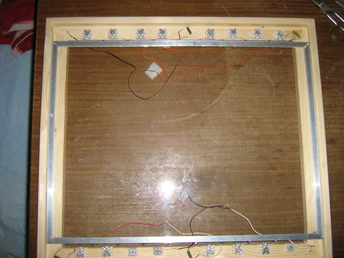
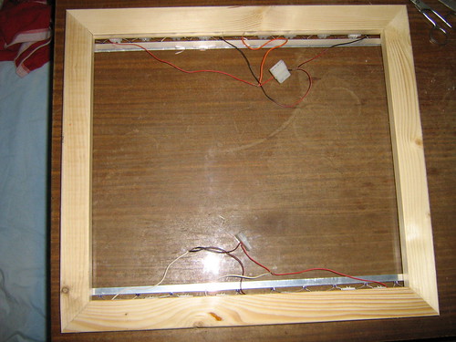
(Above;the front view of the screen)
(Below; the back of the screen)
During the build of my first prototype I used 36 880nm 60 degree 5mm cl IR leds (1,8 V, 20 mA, 11,0 mW/sr).
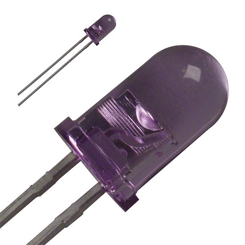
Lateron I discovered that there were leds that were even better, namely the Osram SFH485, specifications: 1.5 V 100(mA) 880 (nm) 5mm. These were a bit more expansive but more powerful, so I would be able to use less leds.
The leds look like this:
I decided to go with 10 leds on both horizontal sides, so 20 leds in total.
After filling in the specifications of the power source and the leds in this led wizard , I found out that, I had to make 4 strings of 5 leds, each with a 47 Ohm resistor of 1 Watt. An electronics teacher at school gave me a few 51 Ohm resistors of 4 or 5 Watt. He told me that would do the job pretty well, since the higher Watt was only about the amount of heat that a resistor could handle. So it would just handle an higher amount of heat without influencing the brightness of the leds. And the difference of 4 Ohm (51-47) was not noticeable, according to him.
I connected the leds on 2 different molex connectors (12 volt), but I might as well have gotten around with just using one.
I just happend to have 2 molex connectors, so I used 2 (which is pretty useless actually).
The wires I used were pretty short, so you might want to use longer ones, so it will be more flexible. I used 0,5 mm thick wire.
I did the entire circuit without soldering, for a change, which seemed to work just fine. So why spend a lot of time on soldering if you can do without.
Image below is a test for the first 5 leds. The green thingie in the top left corner is the resistor.
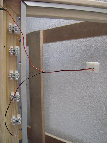
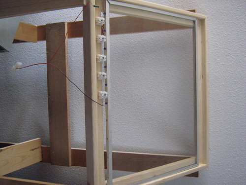
I connected the leds with each other by using strip connectors ("kroonsteentjes" in Dutch).
My first intention was to do the entire setup without the strip connectors and just let the holes in the aluminum rail hold the leds. But because of the fact that some holes were a bit to big (matter of tens of millimeter) to hold the leds pretty steady, I decided to use the strips anyway, because else the leds would be too loose.
You might as well go for the solution below, which is a solderless ledholder. You can easily click the led into this holder, so you won't be bothered with soldering anything. But since I was out of budget and they were too expansive, because they had to be shipped from to UK, I didn't use these.

After connecting all the leds I tested the entire setup by checking for fingers on the computer (image below).
Which seemed to work pretty fine.
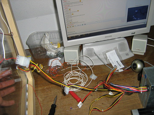
On the left; hand placed on the screen, detected by the webcam on the right (next to the power supply) and displayed on the monitor in the upper right corner.
Note:
With most leds the longest pin of the led is the plus and the short one is the minus. But with these leds it was the other way around. Which I found out because at first, my circuit wasn't working.


 Sho stick
